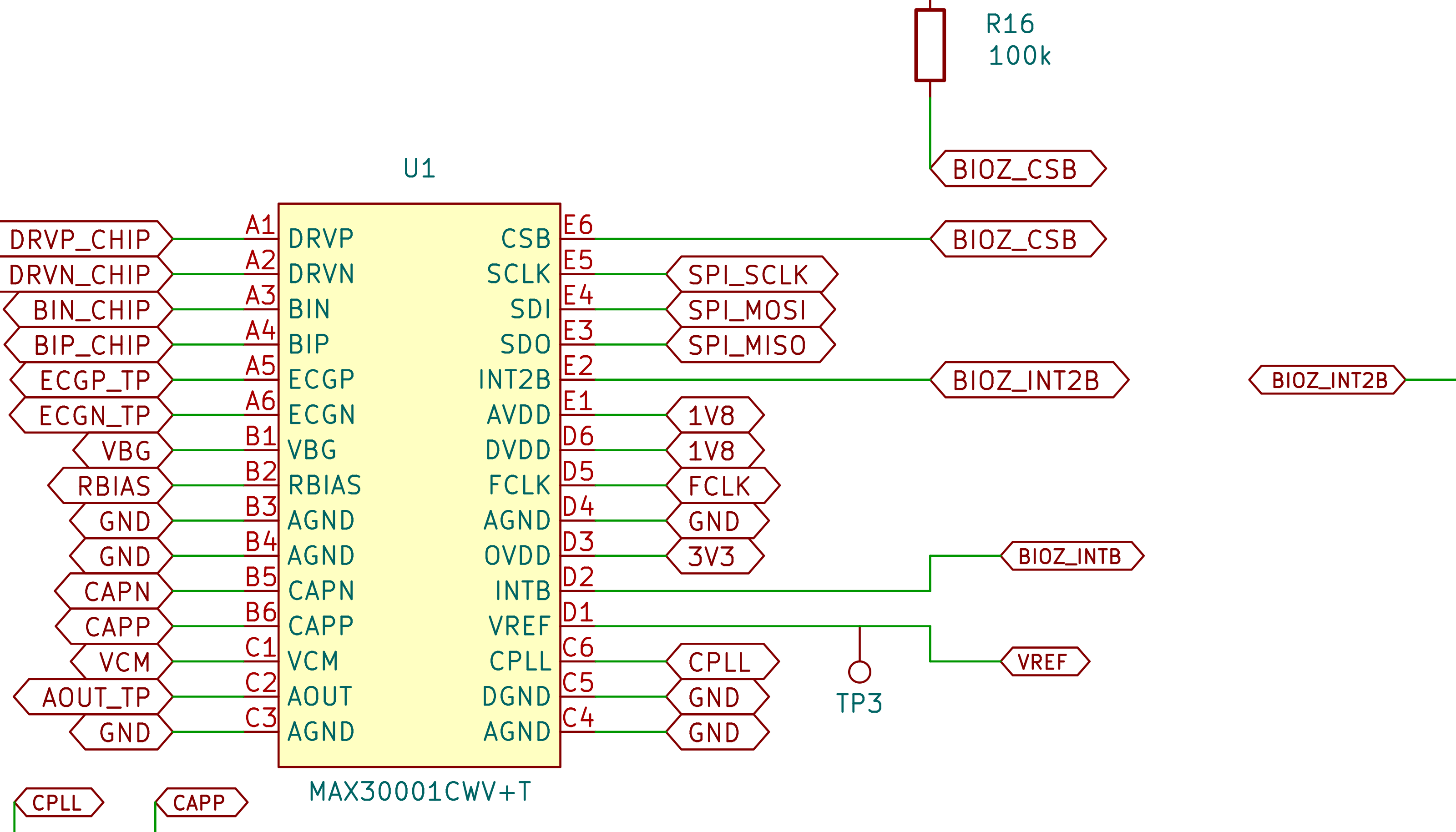
HydroGuard uses four electrodes. The outer pair sends a small alternating current through the upper arm. The inner pair measures the resulting voltage. Separating these two jobs makes the measurement less sensitive to the resistance where each electrode touches the skin.
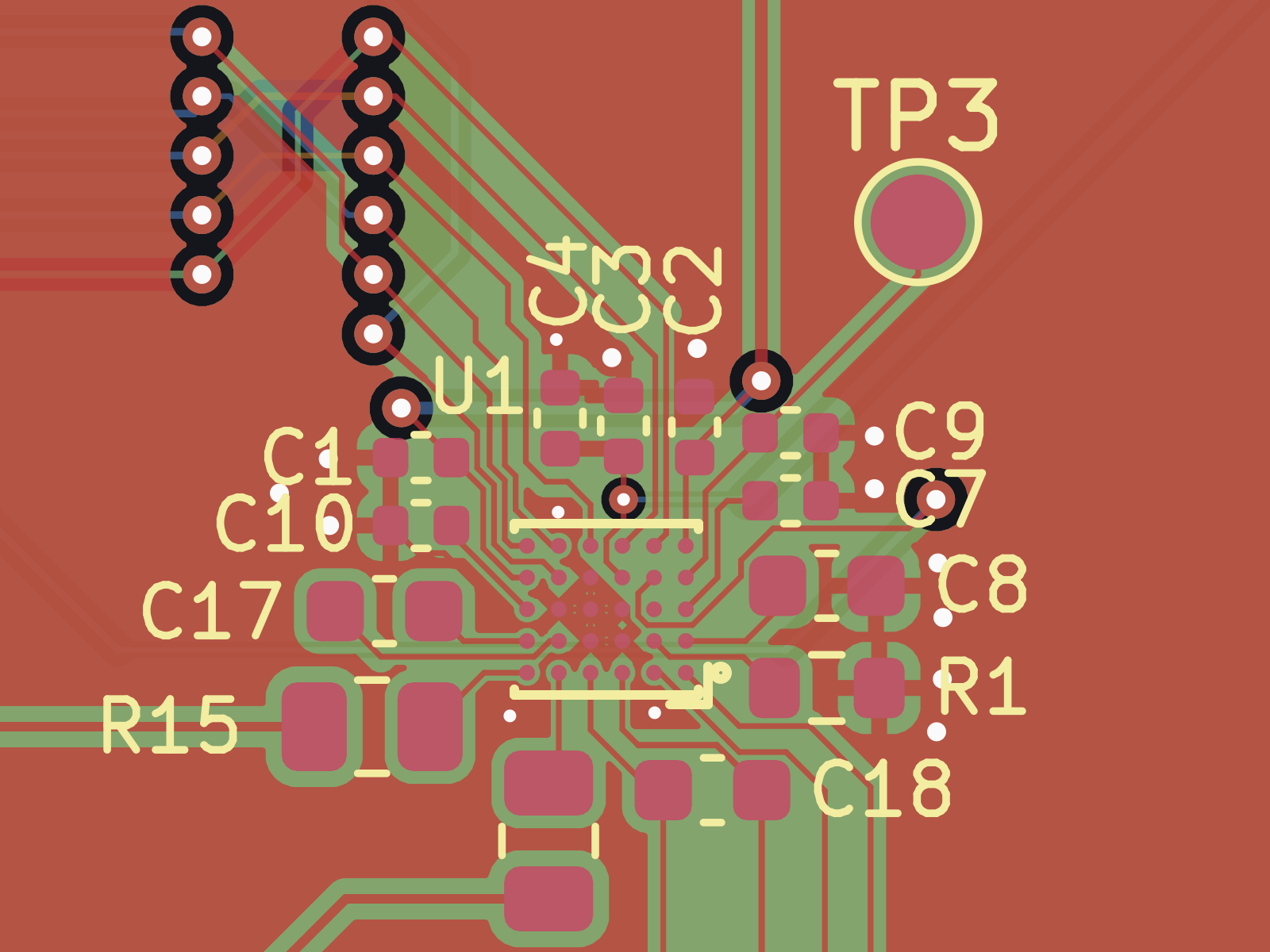
The first board gives the MAX30001 its own 1.8 V supply and clock. Every electrode path has a 1 kΩ series resistor, and the reference voltage has a test point. The ESP32-C6 module is removable, which helped when we needed to probe signals or change the controller.
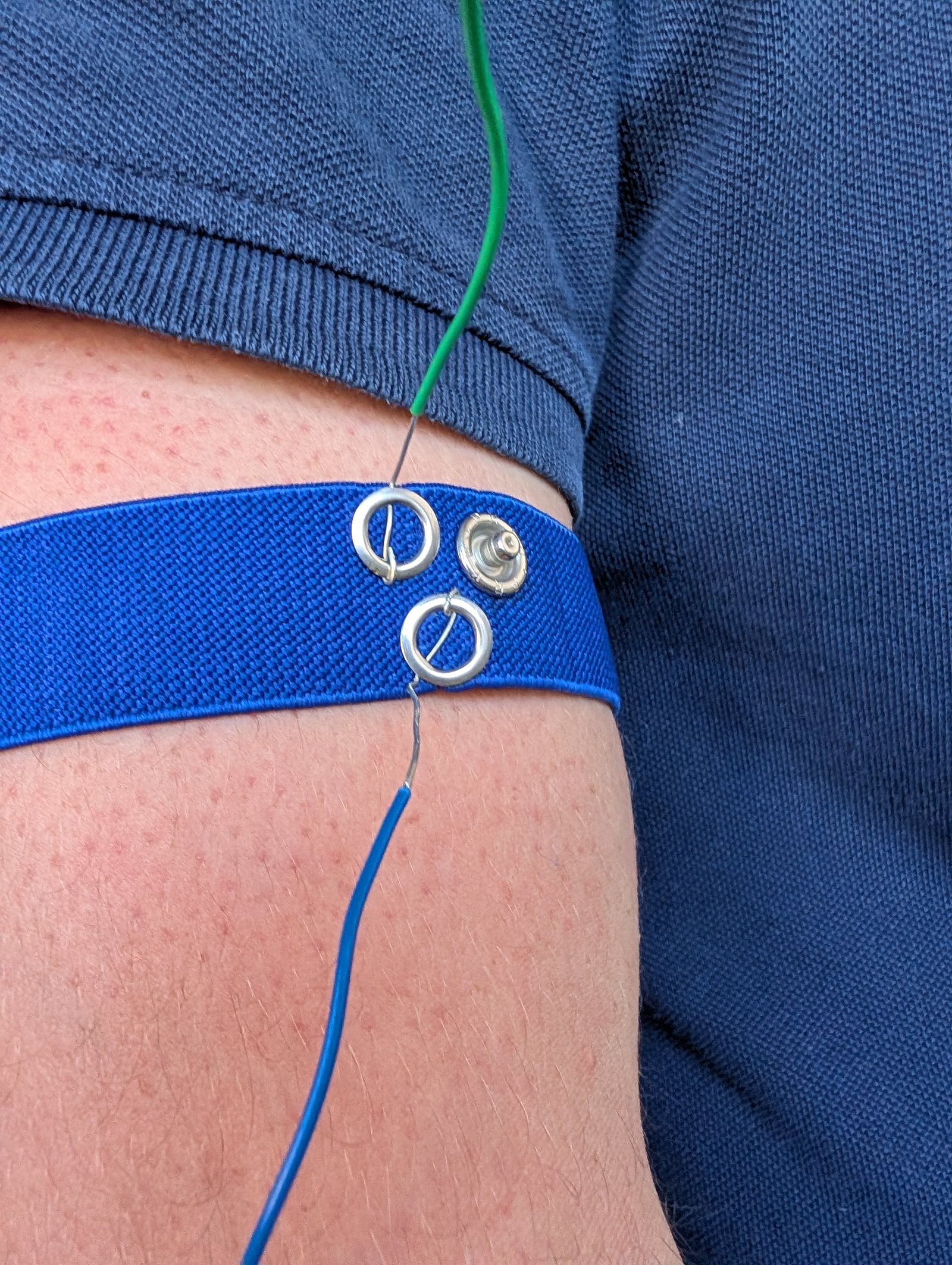
Four electrodes on an elastic band
We use 12 mm sew-on snaps to connect the electrodes. They are easy to replace and easy to position on an elastic band. The band holds them flat against the arm without needing a custom adhesive patch.
Measuring the battery
A 2 MΩ and 1 MΩ resistor divider brings the LiPo voltage into the range of the controller’s analog input. A capacitor beside the input makes the high-resistance divider easier for the ADC to read. The tradeoff is a short settling time before each measurement.
A status light that is not essential
The first board has an SK6812 status LED. It worked, but the board powers it below the minimum voltage in its datasheet. The firmware therefore treats it as optional. If the LED is missing or fails, the impedance measurement still works.
What it cost to have made
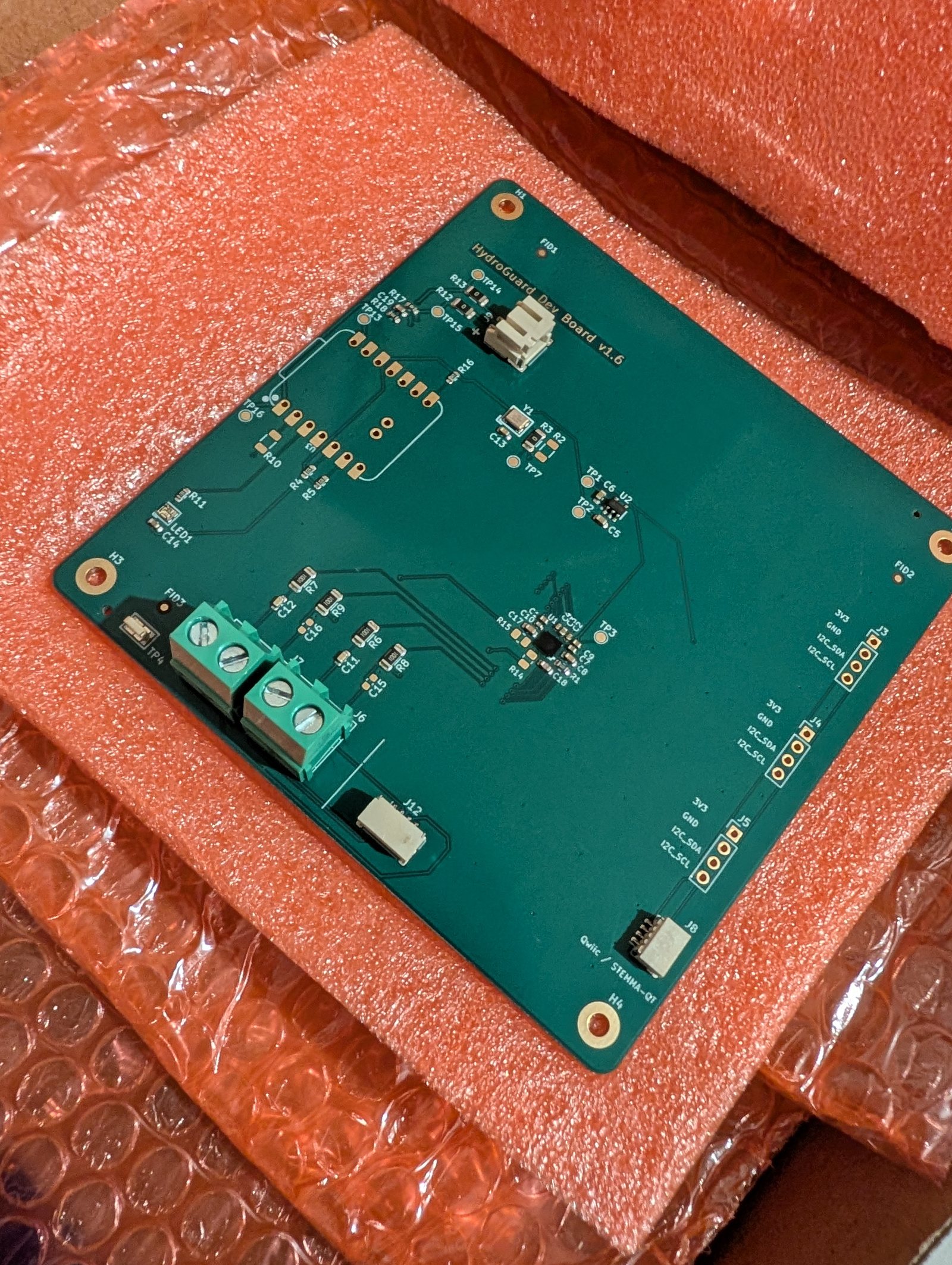
We ordered the boards from JLCPCB on 5 July and had them in hand on 24 July. Four layers, 100 × 100 mm, 1.6 mm FR-4, 1 oz outer copper and 0.5 oz on the inner layers, smallest via 0.3 mm, inspected to IPC Class 2.
The finish is ENIG rather than the cheaper HASL. The MAX30001 comes in a wafer-level package with 0.5 mm pitch, and ENIG gives a flat surface to place that on. HASL leaves domed pads, which is fine for a connector and not fine for this.
We had five bare boards made and two of them assembled, top side only. We shipped JLCPCB our own MAX30001 to fit rather than buying theirs, because it is the one part on the board we did not want to leave to stock availability. The controller module and the I2C headers were deliberately left off the assembly and soldered by hand afterwards, which is also what made the module swappable.
Both assembled boards came back exactly as drawn and both worked. Nothing was misplaced, no joint needed reworking, and the fine-pitch part under the microscope looked like the footprint we sent. For a first four-layer board from a team that had not had one made before, that mattered more than the price did.
A bare board was €4.30 and an assembled one €35.04. With shipping and 19 percent import VAT the whole order came to €126.37. That is the real number for getting a four-layer board with a fine-pitch part on it built, at a quantity that makes no sense to a factory.
Why we started at 32 µA
The first tests used a 32 µA measurement current. It was a conservative starting point while we checked the electrode contact and the signal range. Higher settings remain available, but they were not needed to prove the circuit.
The large board did its job. It gave us a clear view of the signal path and enough access to fix the first problems. The next board can now focus on size, power use and wearing comfort.